![[Artist's Concept of AXAF]](/images/axmicro.gif) |
CXO Project Science:
Ion Studies
|

Chandra
TRIM Ion Transmission Summary
(21 Oct 1999)
Synopsis:
Energy required for 50% proton transmission through:
- Assuming no-damage-with-HETG-in was because of HETG shielding
implies that damaging radiation is primarily between 80 and 190 keV.
-
Scattering through HETG support structure is a factor in
diluting flux and leads to a higher upper limit. The effective transmission
is 50% at 600 keV when dilution
because of scattering is included.
Energy required for 50% oxygen ion transmission through:
Proton transmission through OBF-S
only
OBF-S: 90 nm Al; 200 nm polyimide
(1.34 g/cm^3); 30 nm Al
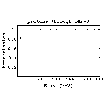
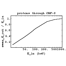
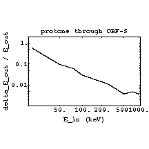
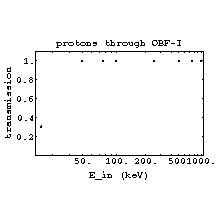
Proton transmission through OBF-I only
OBF-I: 130 nm Al; 200 nm polyimide
(1.34 g/cm^3); 30 nm Al
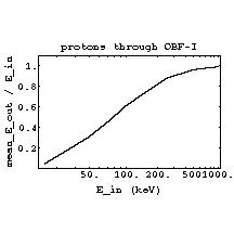
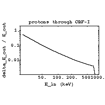
Proton transmission through OBF-S + ACIS-FI gate
structure
OBF-S: 90 nm Al; 200 nm polyimide
(1.34 g/cm^3); 30 nm Al
ACIS Gate Structure: 300 nm Si; 300
nm SiO2; 40 nm Si3N4
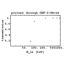
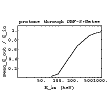
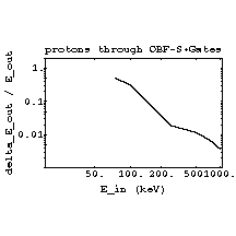
Proton transmission through OBF-I + ACIS-FI gate structure
OBF-I: 130 nm Al; 200 nm polyimide
(1.34 g/cm^3); 30 nm Al
ACIS Gate Structure: 300 nm Si; 300
nm SiO2; 40 nm Si3N4
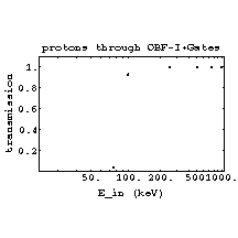
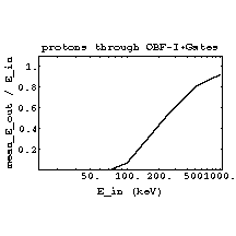
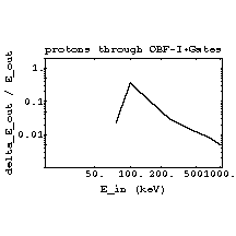 back to
start
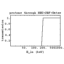
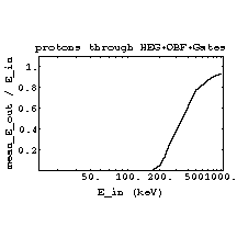
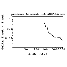
Proton transmission
through HEG substrate+OBF+ACIS-FI gate structure
HEG: 20 nm Au; 5 nm Cr; 1000 nm
polyimide (1.34 g/cm^3)
OBF-S: 90 nm Al; 200 nm polyimide
(1.34 g/cm^3); 30 nm Al
ACIS Gate Structure: 300 nm Si; 300
nm SiO2; 40 nm Si3N4
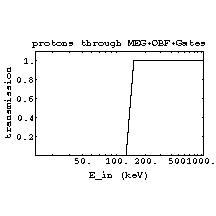
Proton transmission through MEG
substrate+OBF+ACIS-FI gate structure
MEG: 20 nm Au; 5 nm Cr; 500 nm
polyimide (1.34 g/cm^3)
OBF-S: 90 nm Al; 200 nm polyimide
(1.34 g/cm^3); 30 nm Al
ACIS Gate Structure: 300 nm Si; 300
nm SiO2; 40 nm Si3N4
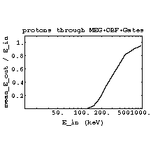
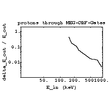 Proton transmission through
HEG substrate
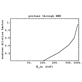
-
Scattering through HETG is a factor in diluting flux
and leads to a higher upper limit. The scatter dilution factor plotted
above is the fraction of total transmitted flux which scatters less than
1°.
-
If we assume that damaging radiation which is scattered
more than 1° misses the ccds while that which is scattered less than
1° can still hit ACIS, then the 50% transmission point increases to
about 600 keV.
-
This transmission combined with another 50% reduction
because of the grating bars, suggests that the HETG has an effective transismission
of only 25% at 600 keV. This significantly weakens the significance of
the suggestion of no damage with HETG inserted during the rad. pass.
Oxygen ion transmission through OBF-S
+ ACIS-FI gate structure
OBF-S: 90 nm Al; 200 nm polyimide
(1.34 g/cm^3); 30 nm Al
ACIS Gate Structure: 300 nm Si; 300
nm SiO2; 40 nm Si3N4
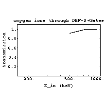
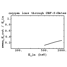
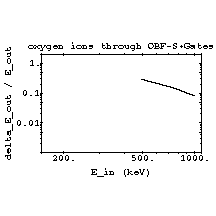
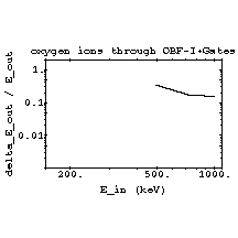
Oxygen ion transmission through OBF-I
+ ACIS-FI gate structure
OBF-I: 130 nm Al; 200 nm polyimide
(1.34 g/cm^3); 30 nm Al
ACIS Gate Structure: 300 nm Si; 300
nm SiO2; 40 nm Si3N4
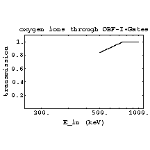
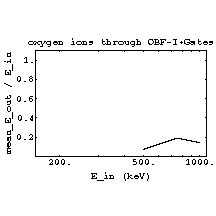
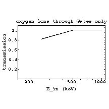
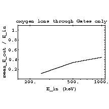
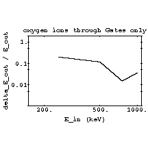
Oxygen ion transmission through ACIS-FI
gate structure
ACIS Gate Structure: 300 nm Si;
300 nm SiO2; 40 nm Si3N4
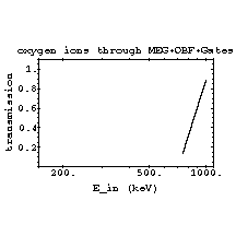
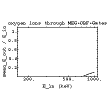
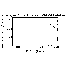
Oxygen ion transmission through MEG
substrate+OBF+ACIS-FI gate structure
MEG: 20 nm Au; 5 nm Cr; 500 nm polyimide
(1.34 g/cm^3)
OBF-S: 90 nm Al; 200 nm polyimide
(1.34 g/cm^3); 30 nm Al
ACIS Gate Structure: 300 nm Si; 300
nm SiO2; 40 nm Si3N4

Go to Chandra Project Science Page or to
X-ray Astronomy at MSFC
![[Artist's Concept of AXAF]](/images/axmicro.gif)
![[Artist's Concept of AXAF]](/images/axmicro.gif)


